

Solar Tracker with an ESP32-C3, A4988 Drivers and Modified 28BYJ-48 Motors
Converting an Old IP Camera into a Home Assistant–Controlled Solar Tracker
In this project, we will repurpose an old IP camera and transform it into a two-axis solar tracker controlled by Home Assistant.
The system will use an ESP32-C3 microcontroller as the main controller, together with two A4988 stepper motor drivers.
The original 28BYJ-48 stepper motors from the IP camera will be modified from their original unipolar configuration to operate as bipolar stepper motors, making them compatible with the A4988 drivers.
The motors are the familiar 28BYJ-48 5 V stepper motors, rated at approximately 0.15 A. They are inexpensive, compact and, thanks to their internal gearbox, provide considerably more torque than their tiny size suggests.
That made them interesting candidates for a small two-axis solar tracker.
The idea was simple:
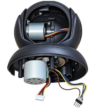
– an ESP32-C3 Super Mini calculates the position of the sun,
– two A4988 stepper drivers control the motors, one for azimuth and one for altitude,
– and ESPHome/Home Assistant provides the software interface and the sun positions.
The finished system can therefore automatically follow the sun throughout the day.
The basic architecture
The tracker has two mechanical axes:
Azimuth (Rotates the solar panel horizontally from east to west.)
Altitude (Tilts the panel vertically according to the elevation of the sun.)
The A4988 modules provide the power switching and current regulation required by the stepper windings.
The standard 28BYJ-48 is a unipolar stepper motor with five wires.
The usual wires are: Orange, Pink, Yellow, Blue, Red
The red wire is the common connection between the two windings.
For an A4988, however, we want a conventional bipolar stepper connection, with two independent windings.
The 28BYJ-48 are unipolar and therefore should be modified so that the two windings become electrically independent.
There are several descriptions of this modification online. The important electrical principle is the same: the common connection must be isolated so that the two coils can be driven independently by the two H-bridges inside the A4988.
The essential requirement is to isolate the common connection between the two windings. Once the common connection is isolated, the red wire is simply no longer part of the bipolar motor circuit.
Also, wire colors and connector arrangements can vary between manufacturers. Measuring the resistance between wires before modifying the motor is therefore a very good idea.
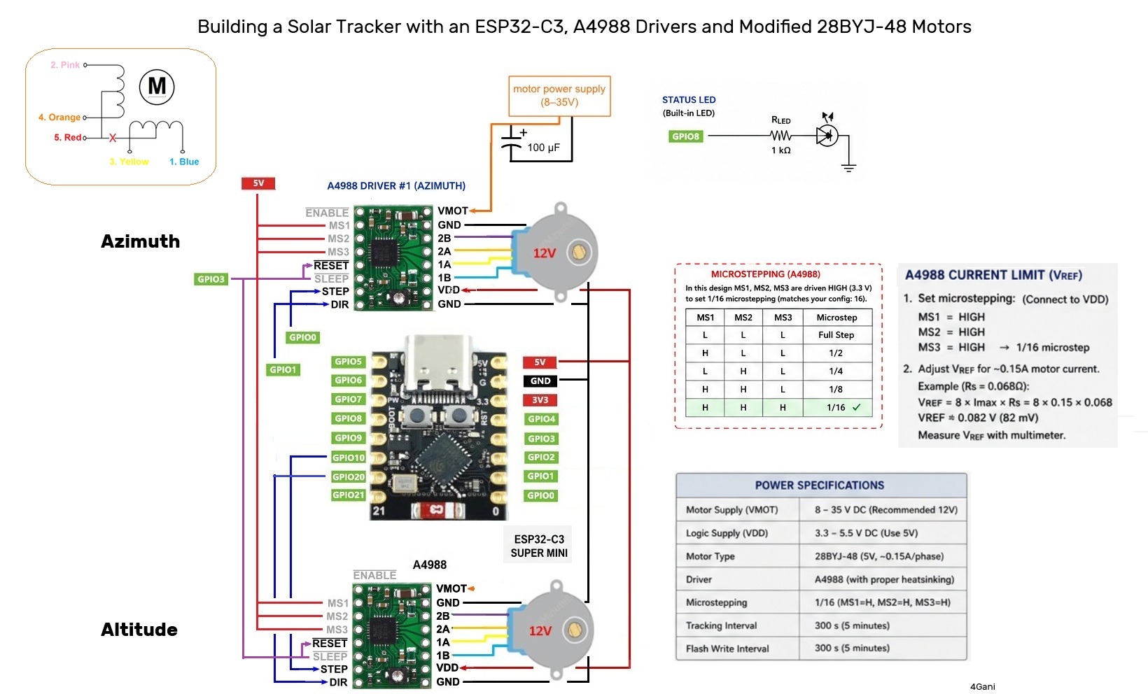
Re-arranging the motor connector
Once the motor has been converted to bipolar operation, I wanted to eliminate additional jumper wires and make the motor directly connectable to the A4988.
The original connector contains five wires. After the modification, only four motor wires are required.
Always verify the actual coils with a Multimeter.
For my motors, I arranged the connector as: Orange / Pink / Yellow / Blue and the red wire is no longer connected.
Measuring resistance is also an excellent method for identifying the coils before connecting anything to the A4988. The value is around 45 ohms.
If the motor rotates in the opposite direction from what is required, Simply reverse one coil pair or use inverted in code to change it.
Using an A4988 with a 5 V motor
The motor is rated for approximately 5 V, while the A4988 requires a considerably higher motor-supply voltage.
The A4988’s motor supply, VMOT, must be between 8 V and 35 V.
So the motor is not connected directly to 12 V.
The A4988 uses its internal current-regulation system to control the current flowing through the motor windings.
This is one of the advantages of a chopper-type stepper driver: the motor voltage and the current limit are not simply the same thing.
Setting the A4988 current limit
The 28BYJ-48 is a very small motor. Setting the A4988 to several hundred milliamps simply because the driver is capable of supplying that current can overheat or damage the motor.
The A4988 uses the voltage at its VREF pin and the current-sense resistor on the particular carrier board to determine the current limit.
The general relationship given by Allegro is:
VREF = 8 × I_MAX × RS
* I_MAX = desired current limit
* VREF = voltage measured at the driver’s VREF point
* RS = current-sense resistor on the particular A4988 carrier
Different A4988 carrier boards use different current-sense resistors. For example, Pololu’s current A4988 carrier uses 0.068 Ω sense resistors, while older versions used different values.
Therefore, the correct VREF must be calculated from the actual A4988 board being used.
For a motor with a target current of approximately 0.15 A:
VREF = 8 × 0.15 × RS
For example, with: RS = 0.068 Ω
the theoretical value would be approximately: VREF ≈ 0.082 V
Always identify the sense resistor on your actual A4988 board and calculate the value accordingly.
ESP32-C3 and saving GPIO pins
The ESP32-C3 Super Mini is surprisingly powerful for its size, but GPIO availability becomes important when two stepper drivers are involved.
Fortunately, the A4988 only requires two primary control signals for normal operation:
STEP & DIR
4 x GPIOs for two motors
There is no reason to use separate SLEEP signals if both motors always operate together as one system.
Therefore, the two A4988 SLEEP inputs can share one GPIO and this saves one GPIO.
Microstepping without using additional GPIOs.
Therefore, we want 1/16 microstepping permanently and can simply connect
MS1 ── VDD
MS2 ── VDD
MS3 ── VDD on both drivers.
For this project, where the motors move relatively slowly and the objective is smooth positioning rather than maximum speed, permanently selecting the desired microstep mode is a very practical solution.
The exact power arrangement depends on the ESP32-C3 Super Mini board you are using.
The motor supply ground and ESP32 ground must be common so that STEP and DIR signals have a defined reference.
Also remember that the A4988 motor supply requires local decoupling. The carrier documentation specifically recommends appropriate capacitors close to the driver.
The solar-tracking software
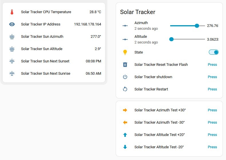
Home Assistant provides the geographical position, while ESPHome’s `sun` component calculates the sun’s position.
Two values are particularly important: Sun Azimuth, Sun Elevation. The ESP32 converts these angles into stepper positions.
There is no reason for the panel to move every second.
The sun moves slowly across the sky, so a tracking update every few minutes is more than adequate for a small solar tracker.
I therefore changed the tracking interval to: 300 seconds
Every five minutes, ESPHome checks the current solar position and calculates the new motor positions.
For a solar tracker, five-minute updates are a reasonable starting point. The interval can later be changed depending on the mechanical accuracy and the size of the solar panel.
Instead of constantly writing the position, the tracker can save the position much less frequently.
A stepper motor normally does not know its absolute mechanical position. After a power failure, the motor itself does not know whether it is physically at 0°, 90° or 180°.
One solution is to install limit switches and perform a mechanical homing procedure.
For example: preferences: flash_write_interval: 5min
The exact value should be chosen according to how much position recovery is required after a power failure.
We save the value to flash memory every 5 minutes. This reduces unnecessary wear on the flash memory while still allowing for recovery after a restart.
The tracker parks the panel after sunset.
Once a week, the software can use the parking position as a reference and reset the stored position.
For true positional calibration, especially if the tracker can be moved by wind or manually, physical limit switches or a homing sensor are the better solution.
The source code is checked into GitHub at: solar-tracker


Leave a Reply