
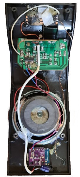
DIY Smart Speaker for Home Assistant
This project focuses on building a smart speaker using an ESP32-S3 Zero, programmed with ESPHome, for seamless integration with Home Assistant.
This device serves as a versatile tool to announce text-to-speech messages, play voice and sound alerts, door chimes, and stream music and online radio directly through Home Assistant.
It works perfectly with built-in Home Assistant functionalities like Media Player and Google TTS.
To ensure optimal audio quality and volume, we’ve opted for a USB-powered active speaker.
This is because speakers connected directly to the Max98357 amplifier tend to have poor sound quality.
Active speakers are ideal for this DIY project as they include a built-in amplifier.
Here are the components for this smart speaker:
- ESP32-S3 Zero microcontroller
- MAX98357 I²S Amplifier
- USB-powered active speaker box (e.g., 2x3W 5V AD8403)
- WS2812B LEDs (for visual indicators or effects)
- USB 5V DC power supply
MAX98357 I²S Amplifier Overview
The MAX98357 is a digital pulse-code modulation (PCM) input Class D amplifier.
It effectively combines an I²S DAC and amplifier into a single, compact breakout board with sampling rate of 8kHz to 96kHz.
The output is a 330KHz PWM square wave, with its duty cycle directly proportional to the audio signal.
I²S (Inter-IC Sound):
This is a serial bus interface standard specifically designed for connecting digital audio devices.
It should not be confused with I²C.
Pin Descriptions:
- LRC (Frame Clock): Left/right clock for I²S.
- BCLK (Bit Clock Input): Provides the clock signal for bit-level data transfer.
- DIN (Digital Input Signal): Where the digital audio data is received.
- GAIN: Used for gain and channel selection.
- SD (Shutdown and Channel Select): Controls shutdown mode and channel selection.
- VCC: Power supply input (DC 2.5V-5.5V).
The amplifier’s gain can be adjusted via the GAIN pin. By default, it provides 9dB of gain.
You can set the gain to 3dB, 6dB, 9dB, 12dB, or 15dB by connecting pull-up or pull-down resistors, or by direct wiring.
Gain Settings:
- 15dB: Connect a 100K resistor between GAIN and GND.
- 12dB: Connect GAIN directly to GND.
- 9dB (Default): Leave GAIN unconnected.
- 6dB: Connect GAIN directly to Vin.
- 3dB: Connect a 100K resistor between GAIN and Vin.
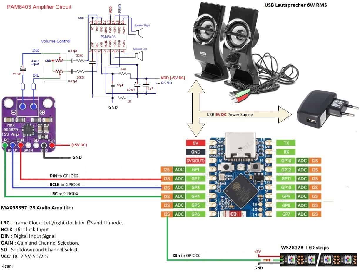
Circuit Diagram:
Below is a diagram showing how I connected the MAX98357 amplifier to the I2S bus of the microcontroller, and then the output of the MAX98357 to the input of the USB speaker.
A simple example you can use to display media with a custom mini media player card.
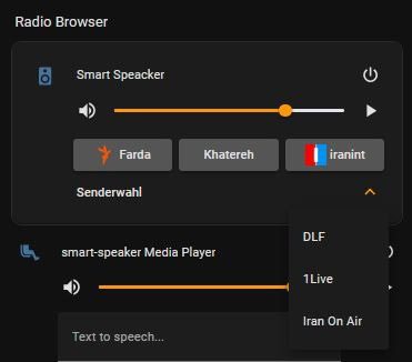
You can select the media player from a drop-down list.
Alternatively, you can add buttons for selecting and streaming online radio stations, as well as configure other settings such as the sound mode, volume controls, media source display, and graphic display.
The source code and for an example of a card is checked into GitHub at: Source Code